Baja SAE — Braking
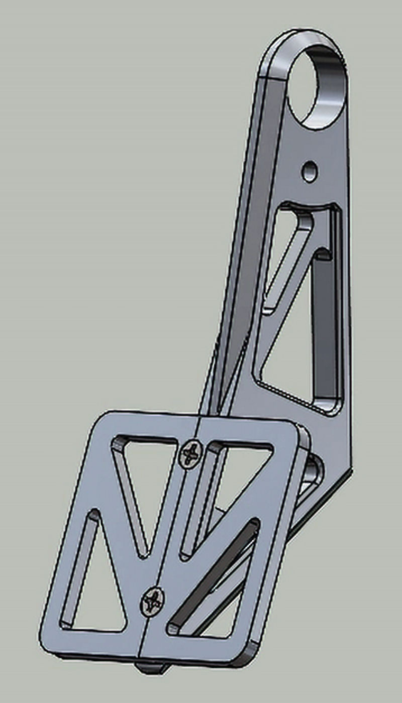
For the 2024–2025 GW Baja SAE car, I designed and machined the brake pedal from scratch. The constraints were tight: it had to fit in a compact cockpit, meet the SAE 2000 N load requirement, keep deflection low enough for a consistent pedal feel, and be straightforward to machine and replace if damaged at competition. The design priorities were strength, ergonomics, and manufacturability.
I started with our team's brake calculator to find the pedal ratio required to generate enough master cylinder pressure to lock the wheels. SAE mandates a minimum pedal input of 2000 N, and I cross-checked that against force data from member testing to make sure the ratio was realistic for an average driver.
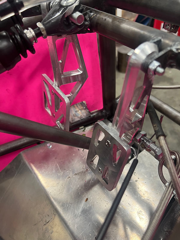
The geometry was then modeled to align the pivot and clevis directly with the master cylinder, minimizing side loading on the master cylinder rod. Packaging was tighter than expected — physical mockups in the cockpit caught a couple of clearance issues before any material was cut, which saved a redo. The final configuration prioritizes simplicity and rigidity, with a predictable, linear pedal feel from light braking through full lock.
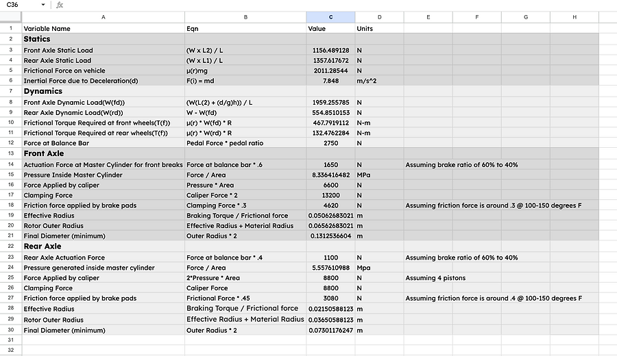 Brake calculator used to determine pedal ratio and minimum rotor sizing
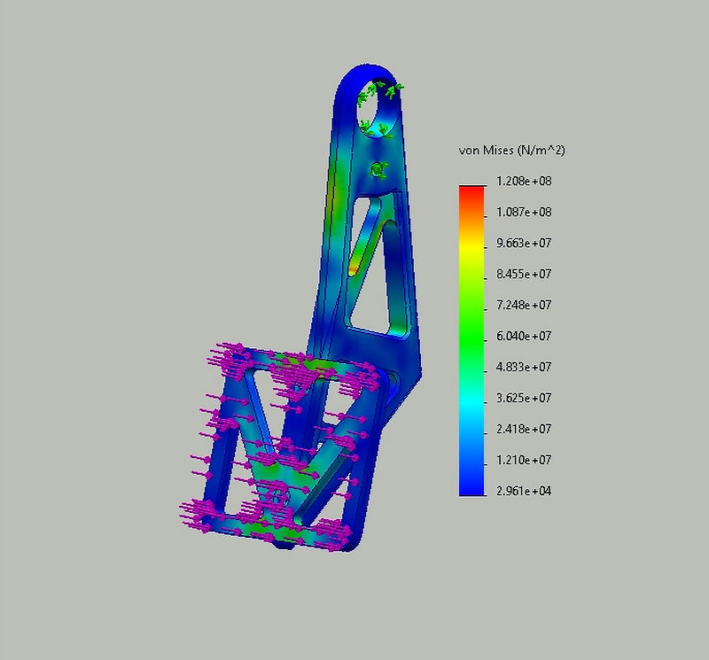
FEA under the full 2000 N load was used to guide wall thickness, fillet sizing, and material distribution. The results showed maximum stress well below the yield strength of 6061-T6 aluminum, confirming adequate safety margin without over-building. Total deflection under load was low enough that the driver gets a consistent, predictable pedal feel through a full stop — no sponginess as the pedal loads up. This was an explicit goal given driver confidence is directly tied to braking consistency in competition.
The pedal is machined from two pieces of 6061-T6 aluminum, selected for its strength-to-weight ratio and machinability. I chose a bolted two-piece design rather than welding for two reasons: welding would risk distorting the precision bores, and a bolted design lets us swap a single piece if one gets damaged at competition rather than replacing the whole assembly.
The pivot bore and clevis mounting points were held to tight tolerances to maintain the geometry that the brake calculator assumed. Any slop there translates directly into unpredictable pedal ratio variation.
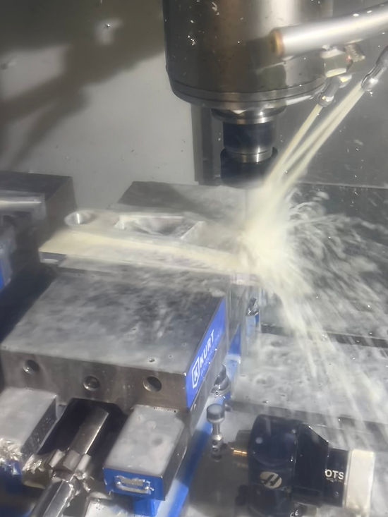
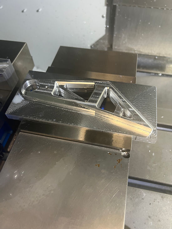
Explore the CAD model in 3D — rotate, pan, and zoom.