Baja SAE — Drivetrain
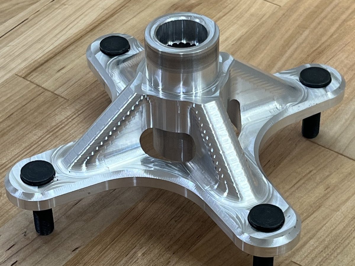
The original wheel hubs were a two-piece assembly: a 6061-T6 hub bolted to a separate 7075-T6 spline adapter. Both pieces were needed because we didn't have a way to machine internal splines in-house, so the adapter was sourced externally. As drivetrain lead, I redesigned the hub as a single piece in 7075-T6 and built the process to cut the splines ourselves.
Consolidating the hub and adapter eliminates the bolt interface between them — one fewer joint to fail under cyclic load, and the geometry is controlled by a single part rather than two. The whole hub is 7075-T6, which is stronger than 6061 under the torsional and bending loads at the wheel.
The internal spline profile was based on COTS CV-joint spline geometry so the hub mates with an off-the-shelf axle. Designing around an existing spline standard meant we didn't have to specify a custom profile from scratch — we could pull the geometry from the CV-joint data sheet and machine to it.
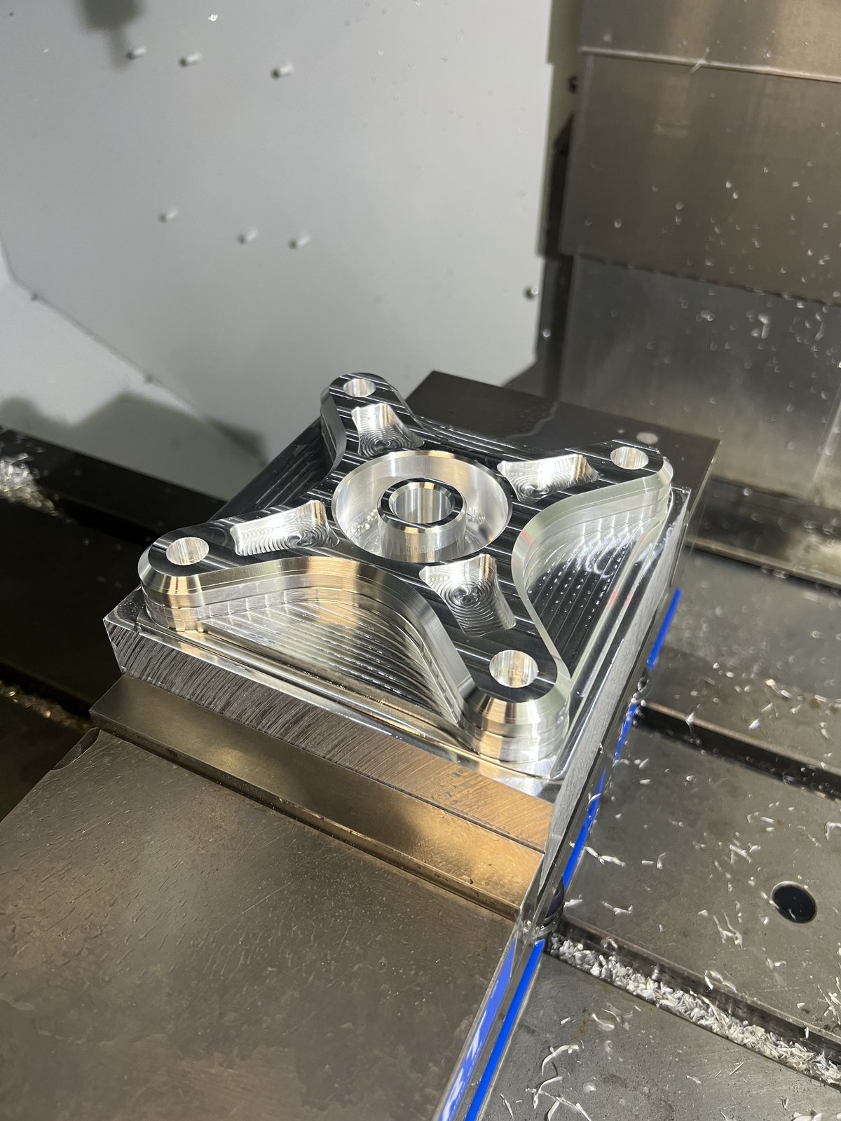
There are two configurations: the front hubs carry the brake rotors, while the rear hubs drop that interface entirely and save roughly 0.1 lb each. Across the design, pocketing between the lug bosses removed 89% of the starting material — about 9.75 lbs — from each blank.
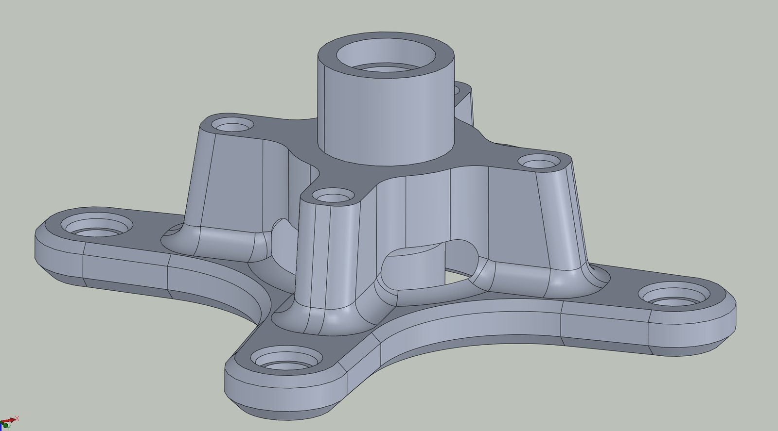
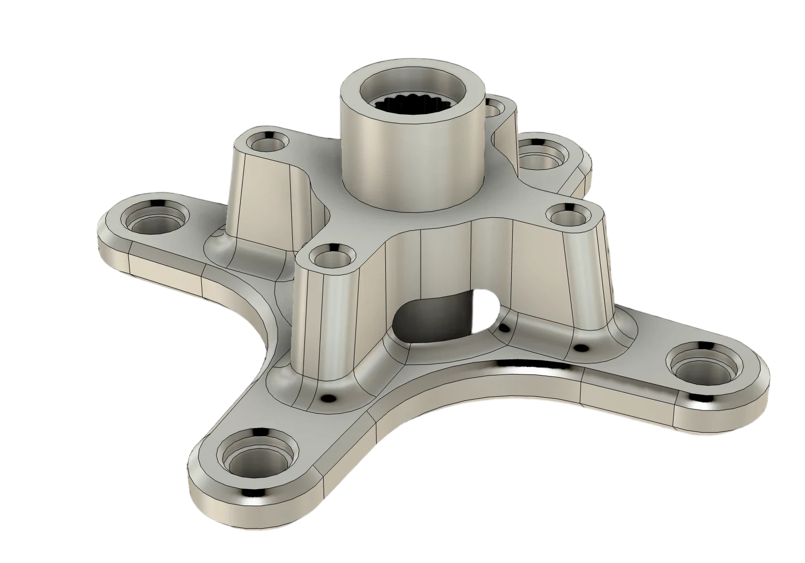
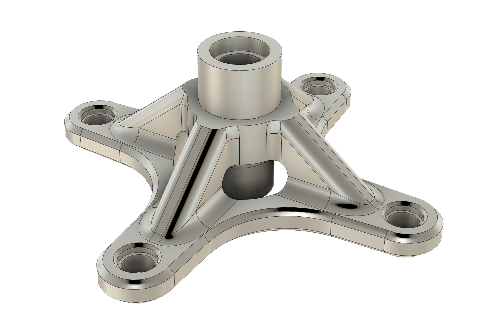
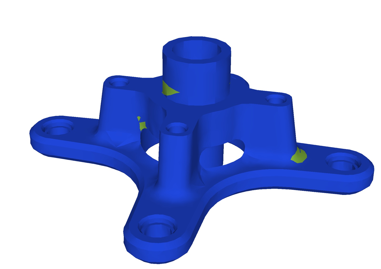
Removing 89% of the blank only works if the material that's left is in the right places. The hub was simulated under worst-case braking and cornering loads to validate the pocketing pattern: stress concentrates around the spline bore and the lug bosses — the regions kept at full section — while the pocketed webs between them stay lightly loaded.
The load path runs from the spline engagement out through the arms to the lugs, so those arms keep their full depth and the pockets live between them where the FEA showed margin to spare.
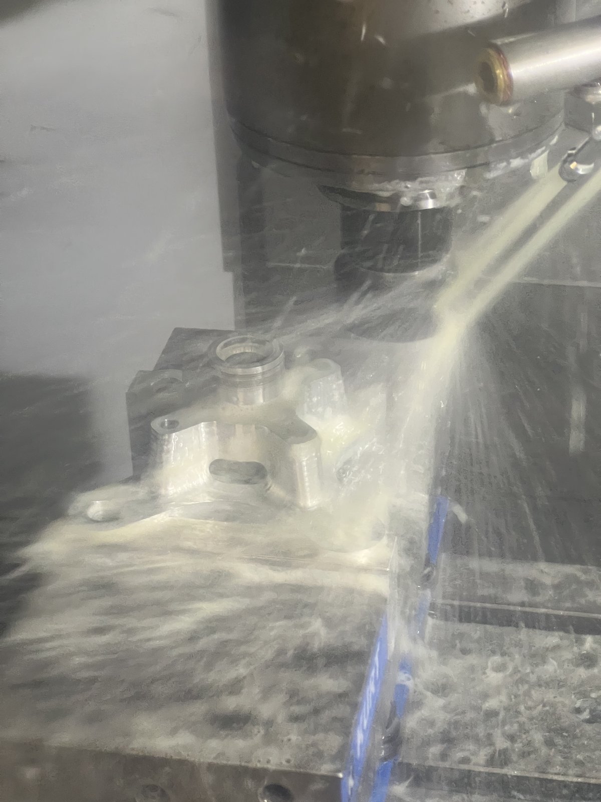
Internal splines can't be cut with a standard end mill — the tooth profile requires a broaching operation. The standard approach is to send parts to a shop with a dedicated broaching machine, which means weeks of lead time and minimum-order quantities.
Instead I developed a CNC broaching process on our Haas Mini Mill using the CV-joint geometry data as the basis for the toolpath. The mill's spindle lock lets you step the tool through the spline profile incrementally, one tooth pass at a time. It's slow compared to a dedicated broach, but it runs unattended and we own the machine.
Result: spline lead time went from weeks to hours, and we can run replacements in-house if a hub gets damaged at competition.
Explore the CAD model in 3D — rotate, pan, and zoom.